WELDING EQUIPMENT
WIRE MESH WELDING EQUIPMENT
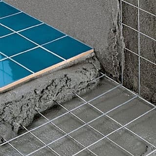
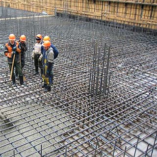
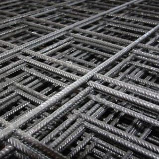
Welded reinforcement and masonry mesh, also known as construction mesh, is used for reinforcement of brickwork, foundation screed, plastering works. Besides, such grid is used for fencing of building objects, manufacturing of various pens, enclosures and cages in livestock industry and on poultry farms. In agricultural complexes, the welded mesh is used as a frame for greenhouses. Welded mesh can be used for reinforcement of reinforced concrete structures, monolithic slabs and coatings, monolithic belts, protective steel fences, reinforcement of existing overlaps during reconstruction, any other purposes where it is necessary to install fittings.
Specialized equipment is used in production of reinforcement base. The principle of its work is to weld parallel and intersecting at an angle of 90° wire strings with a diameter of 3 - 5 or 8 mm.

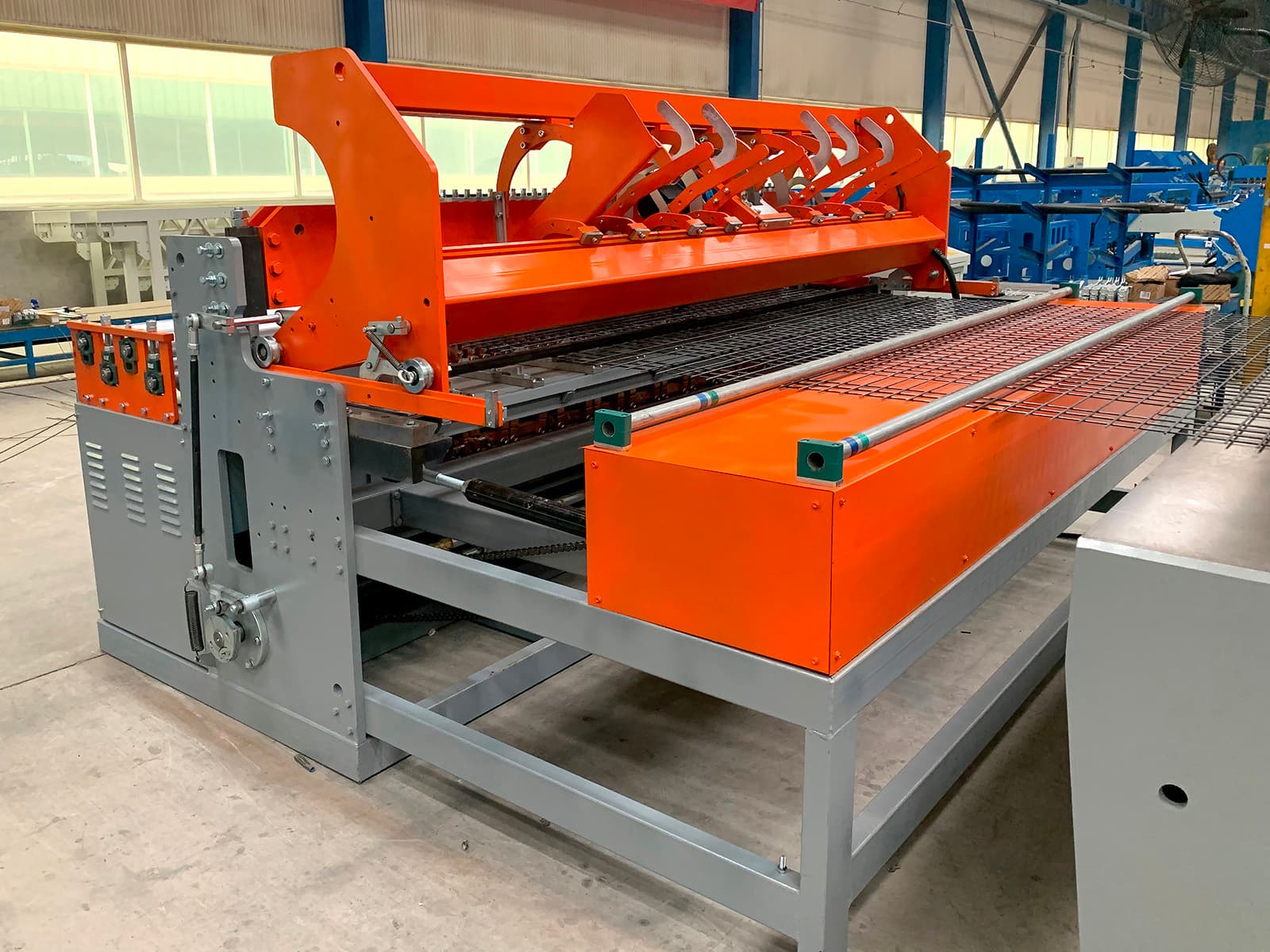
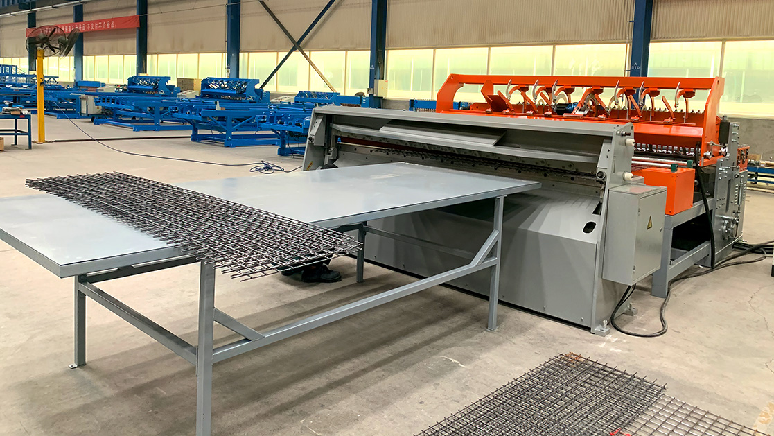
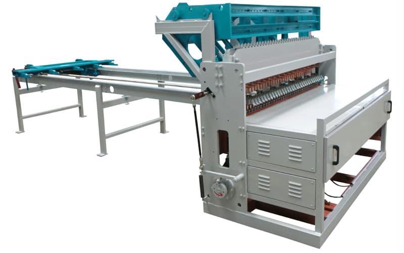
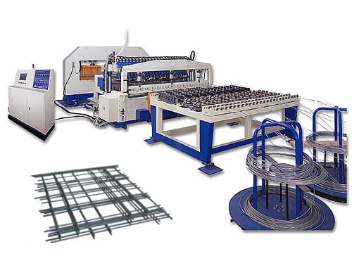
FULL AUTOMATIC WELDING MACHINE R-2500D
Main Characters
- The machine adopts electrical and electronic synchronous control technique both welding time and cent-control welding is composed of digital and integrated electric circuit.
- This operation is accurate, it has stable function, firm welded point and without welded tracks. Not only welding speed is fast but also it is easy to learn and operate.
- The machine is equipped with precise equipment for weft cutting (patented) and position (patented), so the length of wefts is identical and regular, it is unnecessary to slice the side, mesh panel.
- Drawing system adopts elastic tension link (patented) and mesh opening positioning device.
- It is easy to regulate mesh hole and mesh opening size is rather accurate, welding aperture could adjust randomly within certain range.
- The line wires are from the coil and the cross wires are falling automatic from the wires hopper.
Main Technical Parameters
| Name | Parameter |
|---|---|
| Wire diameter | Ø2.0 - Ø5.0 mm |
| Line wire space | 50 - 200 mm, adjustable |
| Cross wire space | 50 - 200 mm, adjustable |
| Max. mesh width | 1500 mm |
| Mesh length | As required |
| Number of electrodes | 31 |
| Transformer | 125 KVA × 4 sets |
| Welding speed | 50 - 70 crosswires per minute (related to wire diameter and hole size) |
| Line wires form | Coil from wire pay-off |
| Cross wires form | Pre-straight and cut wires fallen by step motor |
| Power | 380 V 50 Hz (could be customized) |
| Power cable cross-section | 150 mm2 each phase (aluminum wire ) |
| Welding time | 10 msec ~ 100 msec |
| Welding voltage | Adjust the welding transformer |
| Material | Galvanized / black wire, low carbon steel wire, rebar wire. Tensile strength ≤550 N/m, Carbon Content ≤0,2% |
| Welding control | SCR of silicon control resistance welding |
| Welding pressure adjust | Adjust the length of beam and also the pressure of the spring |
| Transmission | Power Brake motors |
| Press method | By spring |
| Welding method | synchronous control resistance |
| Pulling mesh method | Elastic tension link |
| Control method | Mechnical |
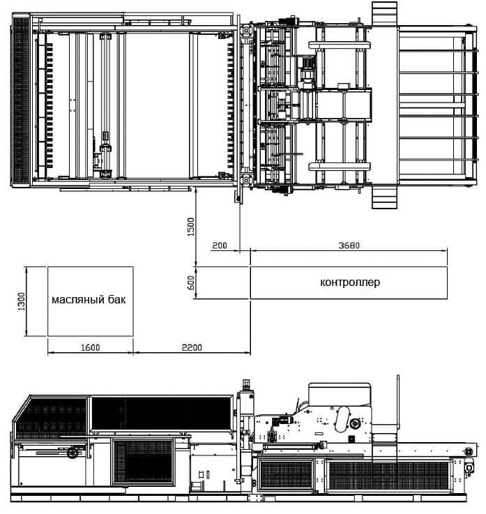
| Overall dimensions (L × W × H) | 3.0 m × 2.0 m × 1.5 m |
| Machine weight | 3 t |
Machine Layout in Factory
List of standard equipment
| Components | Quantity |
|---|---|
| Wire pay-off | 32 pcs |
| Line wire straightening device | 31 pcs |
| Wire straightening and cutting machine | 1 set |
| Welding system | 1 set |
| Mesh cutting machine | 1 set |
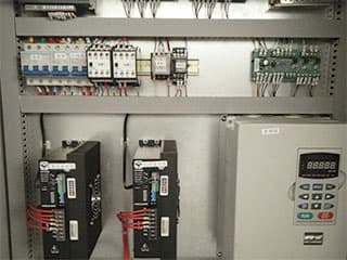
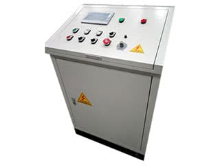
| Electric cabinet and control system | 1 set |
| Spare parts | 1 set |
| Tools | 1 set |
| User’s guide (English version) | 1 set |
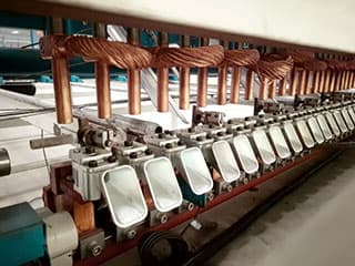
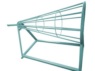
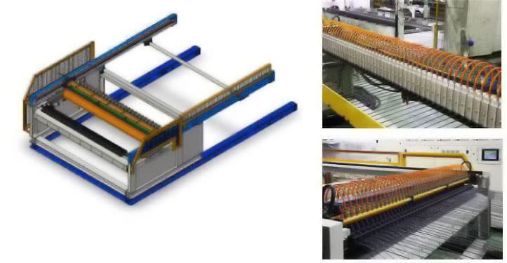
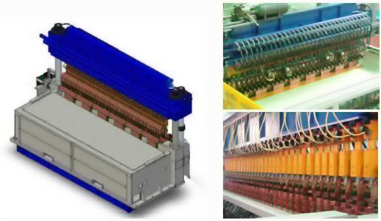
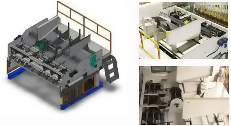
Pictures for reference
Device
and Cutting Machine
Machine
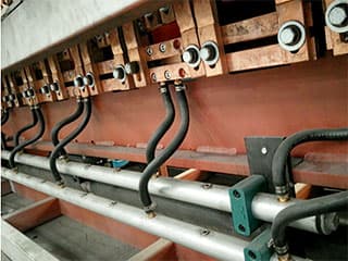
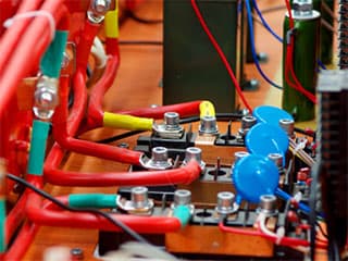
conductive material
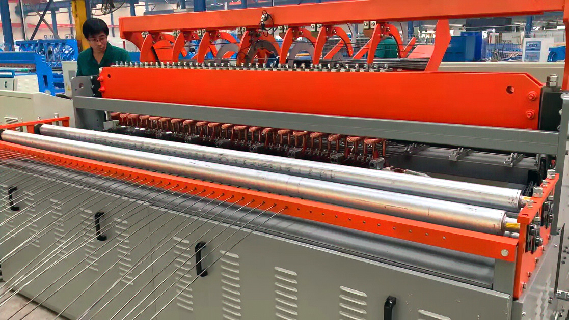
SEMI AUTOMATIC WELDING MACHINE R-2500C
Main parameters of welding equipment
| Number of welding electrodes | 31 |
|---|---|
| Line wire and cross diameters | 2.0 ~ 5.0 mm |
| Line wire space | 50 ~ 200 mm, step less adjustment |
| Cross wire space | ≥25 mm, step less adjustment |
| Reinforced material | low carbon steel wire with carbon content ≤0,2% and tensile strength ≤550 MPa |
| Welding speed | 40 - 60 cross bars per minute (related to wire diameter and mesh hole) |
| Welding transformer capacity | 125 KVA × 4 sets |
| Welding capacity reference | Ø 2-5mm,every transformer can own 8 points,min. aperture 50 × 50; |
| Mode of line wire feeding | Pre-cut,Artificial threading |
| Mode of cross wire feeding | Pre-cut,falling automatically by step motor |
Working condition
| External power supply | 3-phase 380V 50Hz,distance from main control cabinet ≤50m |
|---|---|
| Control voltage | DC 24V |
| Electric capacity | Single control ≥150 KVA |
| Main transformer | Maximum pressure drop ≤10%, Short circuit voltage ≤5% |
| phase cross-sectional area of power supply line | 120 ~ 150 mm2 (Copper wire ) |
| Working condition | Temperature 5 ~ 40 °C, Air relative humidity ≤90% (20 °C) |
| Cooling system | Clean, neutral to slightly alkaline (ph 7 ~ 8) water, Water flow 2 m3/h, Inlet water temperature 25 ~ 30 °C, Inlet water pressure 0,15 ~ 0,3 MPa, Refrigerating capacity 12kw |
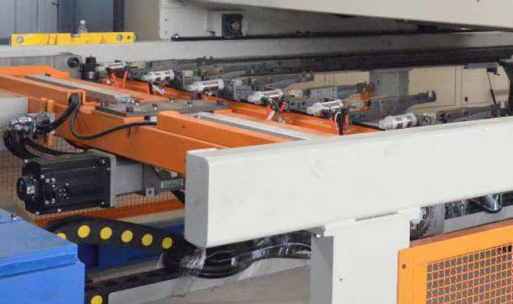
Welding Equipment Layout
- Holding plate
- Main welding machine
- Cross wire hopper
- CNC drag
Main equipment preparation
| Main welding machine | welding system | 1 set |
|---|---|---|
| cross wire positioning device | ||
| line wire positioning device | ||
| control system | ||
| control cabinet | ||
| Optional components | holding platform | 1 set |
| stepladder | 1 set | |
| Cross wire falling | cross wire | 1 set |
| Mesh pulling device | CNC drag | 1 set |
| Round trip mesh pulling device | 1 set | |
| Auxiliary equipoment | Straightening and cutting machine | 2 sets |
| Spare parts | Wear parts such as electrode units, contacts, copper connections, proximity switches, fuses, etc. | 1 set |
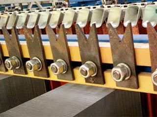
Equipment description
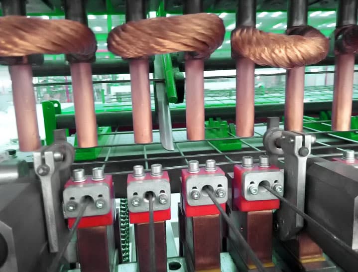
Main welding machine
1The main welding machine is a device to form a welding spot by welding and pressing the positioned line wire and cross wire.

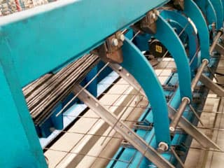
Cross wire hopper
Cross wire hopper is an automatic falling device suitable for a certain length of straightening and breaking material.
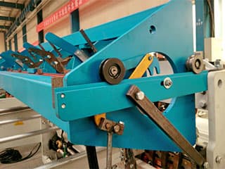
CNC mesh pulling cart
The step mesh pulling mainly of composed of mesh pulling frame,mesh pulling cart and supporting mesh tube.
- Adopt PLC programmable control system, touch screen operation interface.
- Each functional structure is equipped with a fault detection device and has an automatic alarm shutdown function.
- The mesh specifications and operating parameters of each mechanism are set through the touch screen interface.
Auxiliary equipment. Wire straightening and cutting machine
Layout
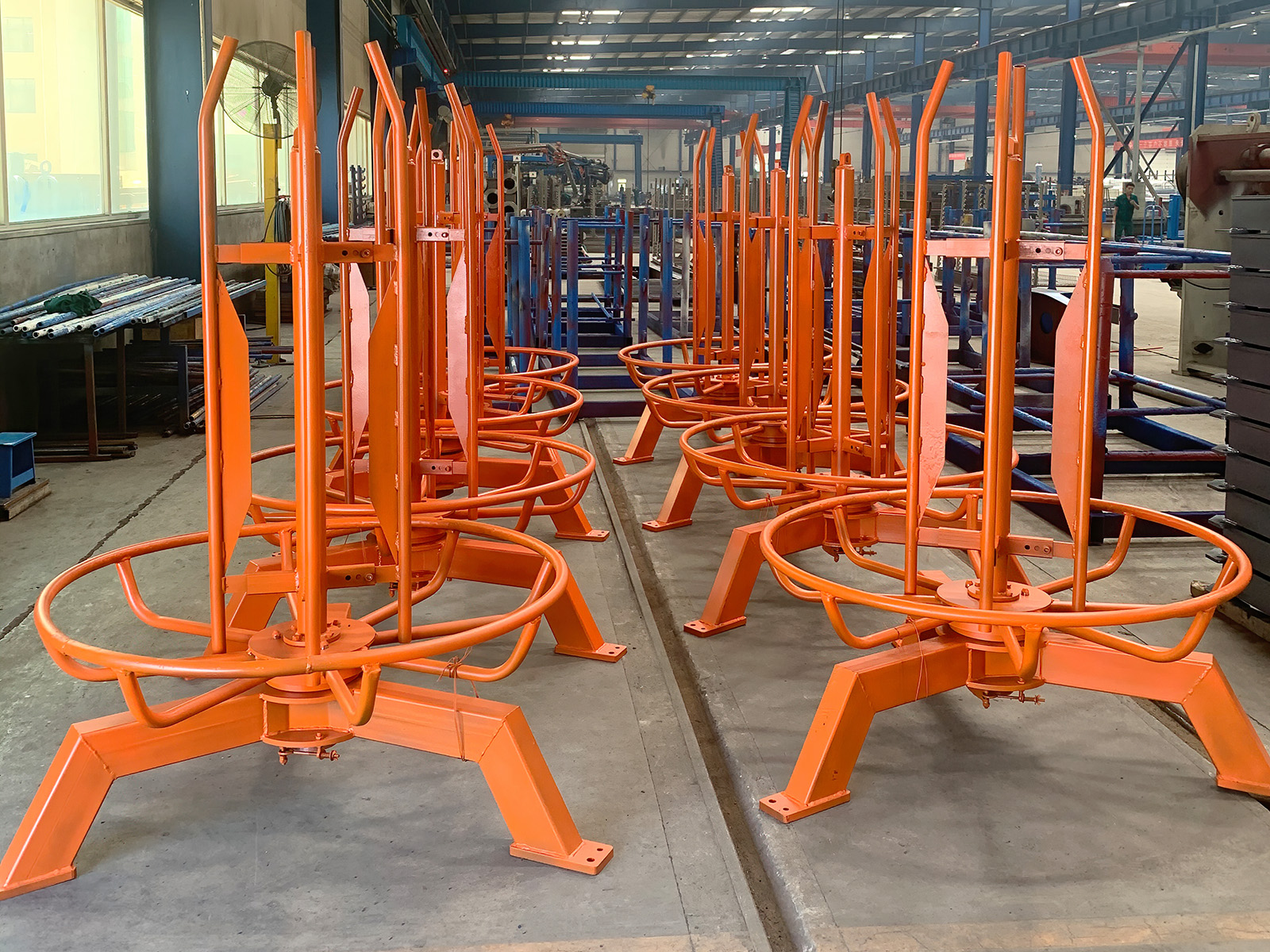
- Payoff
- Safety shelf
- Main straightening machine
- Wire falling runway
Main straightening machine
The main straightening machine is composed of a twisting device, a straightening device, a cutting device and a power transmission mechanism.
Falling runway
The wire falling runway consists of a straight wire runway, a length positioning device,and loading materials.
EQUIPMENT FOR WELDED MESH PRODUCTION RGA SERIES
The design of the equipment for production of welded mesh and metal reinforcement frames of RGA series does not concede to the equipment of such leading foreign manufacturers as Clifford (South Africa), Schnell (Italy), AWM (Italy). At manufacturing of this equipment accessories of leading world manufacturers are widely used. This line of the equipment provides a full cycle of manufacture of a welded grid with high degree of automation of processes, high operational reliability, fast and convenient adjustment.
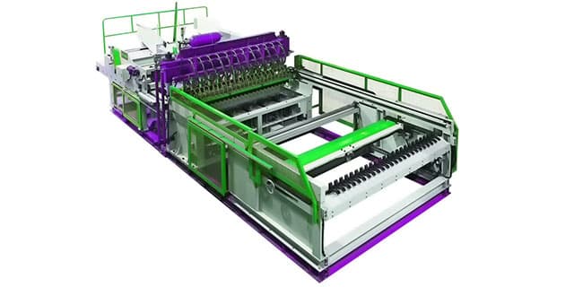
Composition of the welded mesh production line
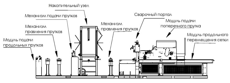
- Longitudinal bar feed module.
- Accumulation unit.
- Welding portal (the main machine of the line, which is responsible for the welding of bars)..
- Cross bar feed module.
- Mesh longitudinal movement module (roller conveyor).
- Option. Guillotine scissors.
- Option. Stacking unit.
- Option. Mesh packer.
- Option. Wire unwinder.
Specification of mesh welding equipment
| Model | Length of longitudinal bars, mm | Length of cross bars, mm | Wire diameter, mm | Line wire space, mm | Cross wire pitch, mm |
|---|---|---|---|---|---|
| RGA-125 | 2000~6000 | 1000~2400 | Ø3~6 | ≥100(50) | ≥50 |
| RGA-200 | 2000~6000 | 1000~2400 | Ø6~10 | ≥100(50) | ≥50 |
| RGA-300 | 2000~6000 | 1000~2400 | Ø6~12 | ≥100(50) | ≥50 |
Energy consumption of equipment for welded mesh production
| Number of welding transformers | 9 pcs |
|---|---|
| Transformer power based on 50% load cycle | 150 KVA |
| Nominal secondary current | 22 KA |
| Secondary voltage | 9 V |
| Number of cylinders | 30 pcs |
| Compressor | power 50 hp, 500 kg/sm2 |
| Distance between electrodes | 95 mm |
| Power supply voltage | 3-phase 380 V 50 Hz±10% |
| Cross section of power supply cable | 300 mm2 for one phase |
| Fuses with delayed actuation | 1600 A |
| Air pressure | 5~8 kg/sm2 |
| Water consumption for cooling | 250 l/min. |
| Water temperature | room temperature ±3°C |
Brief description of mesh welding equipment
Previously cut off cross bars by the straightening machine are fed by the operator to the hopper of the cross bar feed module by means of a girder crane or hoist.
Longitudinal measuring bars are charged directly into the longitudinal bar feed module. This reduces the downtime of the welding machine by loading the bars in the feed position to the welding portal during the production of the previous mesh.
After the start command is given, the mesh starts welding on the welding portal. The mesh is then moved all the way through with the servo drive of the longitudinal module. The baling module stacks the mesh in a stack.
Longitudinal bar feed module
The longitudinal bar loading module allows the loading of bars (maximum 60 pcs) and their feeding to the welding portal during the production of the previous mesh, thus reducing the downtime of the line, increasing the productivity on average by 1.5-2 times.
The longitudinal bar is inserted by the operator manually into the guide bushings. The longitudinal bars are moved to the welding portal by means of a carriage. Wire sensors make it possible to exclude the possibility of manufacturing defective wire mesh.
Accumulation unit
The equipment has 2 sets of wire feeders. The first set is driven by the motor, directing the longitudinal bars into the storage bin (maximum 60 longitudinal bars). The second set is driven by a servo-driven roller conveyor to transfer the longitudinal bars to the welding portal.
Welding portal with cross bar feed module
The welding portal is the main machine of the line. The maximum line capacity, the diameter of the bars to be welded, the geometric dimensions and the mesh design are determined by the characteristics of the welding portal.
The welding gantry is equipped with a cross bar feed module (with a 2 ton hopper), which is fed automatically during welding.
Cubic shaped electrodes made of special material (base - copper, reinforcement additives - TiC, TiO2) allow to increase their service life due to repeated use of faces.
The productivity of the welding portal of 60-80 cross bars per minute (depending on the diameter of the bar), welding speed is 0.5-1.2 seconds.
Control system
The welding equipment control system includes a Programmable Logic Controller and an operator panel with HMI interface. An integrated fault diagnosis system is available. Welding portal operating modes are controlled by a microcomputer using a thyristor converter.
Water cooling system (optional)
For efficient operation of the welding transformer it is necessary to use a water cooling system of the flowing or closed-loop type. The system consists of the following main components: frame, pump, radiator, control unit, water tank.
Guillotine shears (optional)
The hydraulic knife automatically cuts the welded mesh to length.
| Knife material: | SKD11 |
|---|---|
| The range of diameters of the workpiece to be cut: | Ø4.0-8.0 mm |
| Cutting speed: | 45 cuts/min. |
| Cut-off mesh width: | max. 3100 mm |
| Hydraulic motor power: | 20 hp |
Stacking unit (optional)
The unit performs a turn of the welded mesh and transportation to the storage area.
| Roller conveyor length: | 13 meters |
|---|---|
| Interval: | 75×75 mm - 250×250 mm |
| Mesh width: | 1500 mm - 3100 mm |
| Mesh length: | 3500 mm - 6000 mm |
| Mesh weight: | 280 kg (turn) |
| Roller table load capacity: | max. 4200 kg (only for stacking) |
| Turnaround time: | < 20 sec. |
| Unloading time of the finished product: | 15-20 sec. |
Wire unwinder (optional)
The wire unwinder is used when the initial workpiece for feeding longitudinal bars is wire in coils. Capacity - 60 pcs. The wire unwinder is equipped with a motor and a wire feed speed inverter.
Stacker (option)
The main task of the bundling and rolling module is to free the welding portal from the finished mesh. The baler is located directly below the longitudinal transport module, where the stack of mesh is formed. At the end of the production process, the next baler blade is lowered and stacked into a stack.
| Roller conveyor length | 7 meters |
|---|---|
| Mesh interval: | 100×100 mm – 250×250 mm |
| Mesh width: | 2400 mm – 3100 mm |
| Mesh length: | 3000 mm – 6000 mm |
| Height of the tied grid: | 400 mm |
| Bonding speed: | < 35 sec/stacking kit |
| Time to unload the finished product: | 15-20 sec. |
Mesh longitudinal movement module (roller conveyor)
The module of longitudinal mesh movement through the welding portal, because of the use of servo drive, allows to produce mesh with variable pitch of cells. The spacing between the cross bars is set via the control panel and can be changed smoothly.
WELDING LINE FOR COLUMN TYPE WIRE MESH
Options of column type welding wire mesh
- 24 welding cylinders.
- 6 sets of transformers.
- Auto load of the lateral conductor to the tank.
- Transverse pitch 20 ÷ 250 mm.
- Warp wire is loaded into the coiling device and then it is straightened and welded.
- CNC controls drawing and cutting off the mesh.
- After welding process finished wire mesh should be removed from the table.
- Wire diameter: Ø2 ÷ Ø6 mm; Ø6 ÷ Ø12 mm.
- Longitudinal pitch 100 ÷ 250 mm.
- Maximum width of wire mesh - 2400mm.
- Maximum length of wire mesh - 6000mm.
- Performance: 2 sec/wire (performance depends on wire diameter).
SEMI-AUTOMATIC WELDING LINE OF WIRE MESH
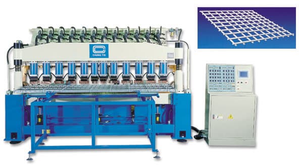
Options of semi-automatic welding line of wire mesh
- 2 sets of 120 KVA transformers.
- Wire diameter: Ø2 ÷ Ø10 mm.
- Performance: 3.5 sec/wire.
- Dimensions of produced wire mesh:
- 2400mm x 3000mm
- 1800mm x 3000mm
- 1200mm x 3000mm
- 12 sets of cylinders controlled independently. Adjustment ability in accordance with the requirements to the product.
- 2 sets of transformers located on both sides of the machine.
- 12 sets of cylinders located in the upper part of the machine.
- Adjustable welding current
- Semi-automatic loading of wires into the shape.
- Welding is started by foot switch.
- High quality final product without any deformation.
AUTOMATIC WELDING MACHINE FOR WIRE MESH
| Min./Max. wire mesh width: | 1000-2600 mm |
| Max. wire mesh width: | 2500 mm |
| Min./Max. wire mesh length: | 1000-6000 mm |
| Line wire diameter (min./max.): | 3.0~6.0 mm |
| Horizontal wire diameter (min./max.): | 3.0~6.0 mm |
| Max. quantity of wires for mesh: | 24 pcs. |
| Line wire pitch: | 50 mm |
| Horizontal wire pitch: | 50 mm |
| Working cycle: | to 60-80 crosswire/min. |
| Brazing speed for one crosswire: | 0.1~1.2 sec (depends on wire diameter) |
MESH WELDING MACHINE RG-200S-2400-24T
Technical Specification
Parameters of the mesh produced
| Min./Max. wire mesh width | 1000 - 2500 mm |
|---|---|
| Max width of welded mesh | 2400 mm |
| Min/max mesh length | 1500 - 6000 mm |
| Transverse wire diameter (min/max) | 5 - 12 mm |
| Cross wire diameter (min/max) | 5 - 12 mm |
| Max crossing thickness | ≤24 mm |
| Max amount of longitudinal wire per mesh | 24 rods |
| Longitudinal wire pitch | 100/150 mm |
| Transverse wire pitch (min) | 50 mm |
| Vertical wire overhang | 25 mm |
Production capacity
| Welding cycle | up to 80 cross bars Ø6 - 7 mm per minute up to 60 cross bars Ø8 - 12 mm per minute |
|---|---|
| Welding speed of cross bars | 0.5 - 1.2 sec. (depends on wire diameter) |
| Time of ejection of the welded mesh, return of the gripping forceps, insertion of longitudinal bars | 3 - 5 sec. |
Workpiece material
Soft steel wire, low carbon wire - straight, without scale. The wire should have a clean surface, without any lubrication or dirt.
Equipment characteristics
| Number of welding transformers | 6 pcs. |
|---|---|
| Transformer power based on 50% load cycle | 200 KVA |
| Secondary current for transformer | 22 кА |
| Secondary voltage | 12 В |
| Number of welding cylinders | 24 pcs (single-impact) |
| Pressure force | 800 kg (hydraulic) |
| Cylinder size | 50 mm |
Requirements for engineering networks and communications
| Power source | 3-phase 380 V 50 Hz ±10% |
|---|---|
| Power cable cross-section | 600 mm² (for one phase) |
| Fuses with delayed actuation | 2000 A (not less than 0.5 sec.) |
| Air pressure | 5 - 8 kg/sm² |
| Air compressor | 5 hp |
| Cooling water consumption | 250 l/min |
| Water temperature | room temperature |
Equipment design
EQUIPMENT CHARACTERISTICS
Manual feeding of longitudinal wire
The main loading platform is a plug-in trolley, which includes fixed guide channels, to where the operator inserts longitudinal wires and rows of fixed locking clamps.
The cart is activated when the operator has finished loading the longitudinal wire. The locking clamps place longitudinal wire that has been loaded and moves it to the welding point. The welding machine automatically continues welding work.
WELDING MACHINE FOR MESH WELDING
In accordance with the welding step, the operator can adjust the upper cylinders and electrodes. Welding time and welding current are regulated and controlled by thyristors and a microcomputer timer for a more accurate electrode pitch and flawless use of electrode arrays. Water-cooled welding transformers are installed at the bottom of the welding machine and are connected to the holding electrode using flexible distribution cables, also cooled by water.
TRANSVERSE WIRE FEEDING
Transverse wire feeding is performed through a special automatic bar loading hopper, which is preloaded manually with the necessary number of straightened and cut wires. The automatic loading carriage for the transverse wire is equipped with a hopper for sorting, positioning and ejecting the wire.
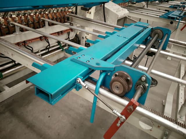
GRIPPING DEVICE FOR WELDED MESH
The device is equipped with a serve-motor and clamping handles that hang the mesh panel of the first row of transverse wire. Then the grippers pull the mesh for the remainder of one meter, based on the size of the transverse pitch.
CONTROL SYSTEM
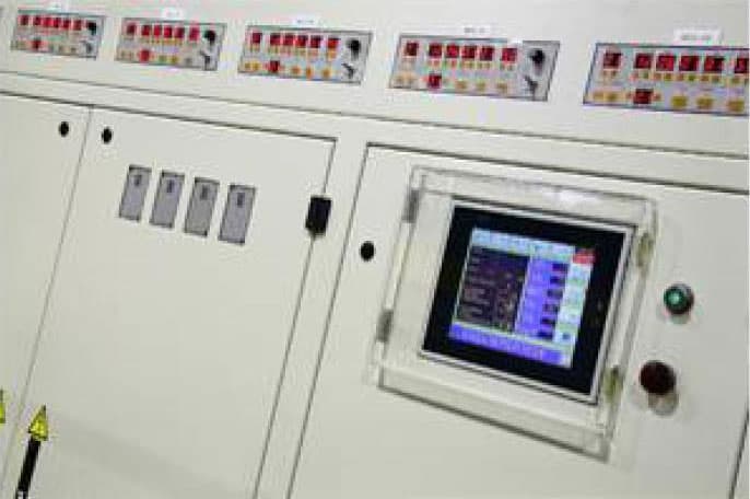
The equipment has a HMI interface that runs on a Windows system and based on a software logic controller (PLC). All parameters are set immediately on the panel. There is a system for diagnosing problems with displaying pictures to quickly eliminate and avoid excessively long stops of the machine. Feeding pushing and unloading of the longitudinal wire are driven by a servomotor with an inverter, while the welding machine itself is controlled by the S.C.R and microcomputer controller. The workflow is connected to the PLC and is displayed on the screen in a graphical form as well as fault notifications.
Trouble analysis:
- Trouble with wire feed
- Lack of wire
- Error when unloading longitudinal bars
- Error in pushing cross bars out
- Failure to feed longitudinal bars forward
- Lack of welding force during servo motor overload
- Incorrect positioning
- Abnormal pneumatic pressure
- Overheating
DEVICE FOR WIRE TURNING AND LAYING (OPTIONAL)
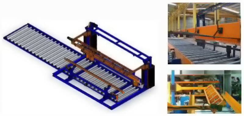
After welding, the mesh is moved by the rollers to the storage area.
| Applicable sizes: | |
| Line spacing | 75 × 75 mm ~ 250 × 250 mm |
| Mesh width | 1000 mm ~ 2600 mm |
| Mesh length | 3500 mm ~ 6000 mm |
| Mesh weight | 280 kg (turn) |
| Roller conveyor load capacity | max. 4200 kg (for styling only) |
| Turning time | less 20 sec. |
| Exit time | 15-20 sec. |
| Roller conveyor length | 13460 mm |
Equipment operation
Welding
- Manual feeding of longitudinal wire.
- Accurate welding step setting (as required).
- The automatic loading carriage for the transverse wire is equipped with a hopper for sorting, positioning and pushing the wire.
- Depending on the wire diameter, the welding time and current can be easily adjusted.
Wire Laying
- The finished mesh will be placed on the stacker.
- When the required height is reached, the operator moves the accumulated meshes using a bridge crane.
- These actions are repeated until the laying volume reaches the required limi.